

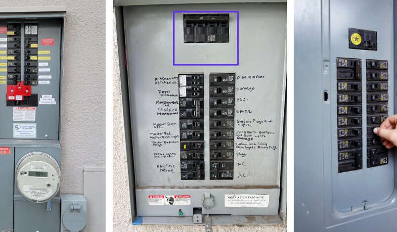

Selecting the correct current capacity for data center power distribution equipment is a critical engineering decision. When designing white space infrastructure or upgrading server room capacity, evaluating choices from a specialized RPP Manufacturer ensures your facility gets a system tailored to actual electrical loads. A Remote Power Panel (RPP) acts as an essential distribution hub between upstream transformers or Uninterruptible Power Supply (UPS) units and downstream server racks. Choosing an incorrect amperage rating introduces severe risks: undersizing leads to continuous breaker tripping and unplanned downtime, while severe oversizing wastes capital expenditure and floor footprint on unused electrical capacity.
Determining the ideal amperage for an RPP requires evaluating server cabinet densities, calculating total continuous loads under electrical safety codes, accounting for 3-phase power delivery, and building in a realistic growth buffer for future hardware expansions.
Below is a practical guide on how to calculate, evaluate, and choose the right amperage for your Remote Power Panel to ensure optimal performance, safety, and scalability.
What Is a Remote Power Panel and Why Does Amperage Sizing Matter?
An RPP is a compact electrical distribution enclosure designed to extend power distribution from main distribution boards directly into server rows. Unlike heavy Transformer PDUs that contain step-down transformers, an RPP focuses entirely on high-density sub-feed circuit management, housing main input breakers, busbars, and 42-pole or 84-pole panelboards.
Choosing the right amperage for an RPP establishes the total power envelope for an entire row of server cabinets. Standard commercial RPP sizes typically range from 225 Amps to 600 Amps per unit.
Sizing the unit correctly ensures that:
-
Circuit Breakers Operate Within Safe Operating Limits: Avoids nuisance tripping caused by continuous heat accumulation in over-subscribed panels.
-
Capital Budgets Are Optimized: Prevents over-spending on oversized copper busbars, heavy feeder cables, and large upstream breakers that exceed real-world demands.
-
White Space Density Is Maximized: Ensures sub-feed panels match the precise density of installed IT cabinets without stranding unused power capacity.
1. Step 1: Calculate Your Total Connected IT Load
The foundation of any electrical sizing calculation is determining the actual power draw of the connected hardware. Server cabinets house various equipment types—from standard 1U/2U web servers to high-draw GPU processing clusters.
Avoid the “Nameplate Trap”
A common mistake when calculating total load is summing the manufacturer nameplate labels on server power supplies. Nameplate numbers reflect maximum theoretical power draw under extreme, synthetic laboratory conditions. In real-world daily operations, enterprise servers typically operate at 40% to 60% of their rated nameplate value.
Using raw nameplate math results in massive over-engineering. Instead, utilize actual historical usage metrics from existing monitoring tools, or request real-world operational power draw specs from hardware vendors.
Aggregate Row Sizing Example
Suppose you are designing an RPP to power a row of 10 server cabinets, with each cabinet drawing an average active load of 10 kW.
2. Step 2: Apply National Electrical Code (NEC) Safety Rules
Electrical safety standards mandate that distribution equipment cannot run at 100% of its rated capacity continuously.
The 80% Continuous Load Rule
Under National Electrical Code (NEC Article 210 and 220) guidelines, a power circuit is considered a continuous load if maximum current draw lasts for three hours or more. Because data center workloads run continuously 24/7, an RPP must be derated by 20%.
This means a panel rated for 400 Amps can only support a continuous load of 320 Amps during normal operations:
To find the minimum required panel amperage rating, take your calculated active load and divide by 0.80:
3. Step 3: Convert Power (kW) to Current (Amps) for 3-Phase Systems
Most enterprise data centers utilize 3-phase power delivery (208V 3-phase in North America or 400V 3-phase globally) to distribute electricity to Remote Power Panels efficiently. To size an RPP accurately, you must convert active kilowatts (kW) into total current (Amps).
The 3-Phase Amperage Formula
To calculate current on a 3-phase AC system, use the standard electrical formula:
Where:
-
Power (Watts): Total kW load multiplied by 1,000.
-
Voltage: Line-to-line AC voltage (typically 208V in North America).
-
$sqrt{3}$ (Square Root of 3): Constant for 3-phase power calculations ($approx 1.732$).
-
Power Factor (PF): The ratio of real power to apparent power. Modern server power supplies feature Active Power Factor Correction, typically operating at 0.95 to 0.99 PF.
Sizing Calculation Walkthrough
Using our previous example of a 100 kW IT load on a 208V 3-Phase system with a 0.98 Power Factor:
-
Calculate Active Operating Current:
$$text{Current (Amps)} = frac{100,000 text{ Watts}}{208 text{ V} times 1.732 times 0.98}$$$$text{Current (Amps)} = frac{100,000}{353.05} approx 283.2 text{ Amps}$$ -
Apply the 80% NEC Continuous Load Safety Factor:
$$text{Minimum Required RPP Rating} = frac{283.2 text{ Amps}}{0.80} approx 354 text{ Amps}$$
In this scenario, a standard 225 Amp RPP would be severely undersized and trip its main breaker. The correct selection for this 100 kW row is a 400 Amp RPP.
4. Step 4: Account for Redundancy and Growth Buffers
Once baseline safety calculations are complete, infrastructure teams must account for system redundancy and future hardware growth.
1. Dual-Feed (A/B) Redundancy Architecture
High-reliability facilities utilize dual power paths (Feed A and Feed B). In normal operations, each RPP carries roughly 50% of the total row load. However, in the event of an upstream UPS or switchgear failure on Feed A, RPP B must immediately absorb 100% of the row’s electrical load without tripping.
When sizing dual-feed panels, ensure that a single panel’s maximum continuous operating capacity (80% rating) can handle the entire combined row load during a failover event.
2. Future Growth Buffer (20% to 30%)
Hardware refreshes almost always increase cabinet power density. Server manufacturers regularly squeeze higher processing power into smaller chassis footprints. Adding a 20% to 30% growth margin to your initial amperage calculation ensures that future server additions won’t require replacing panelboards or pulling new main feeder lines.
5. Step 5: Evaluate Physical Space, Pole Counts, and Panelboard Configurations
Amperage is only one piece of the puzzle; the physical panelboard configuration must also align with your cabling layout and cabinet circuit counts.
42-Pole vs. 84-Pole Panelboard Configurations
RPPs typically house one or two sub-feed panelboards:
-
42-Pole Panels: Standard for low-to-medium density rows using single-phase 20A branch circuits.
-
84-Pole Panels: Ideal for high-density rows where each server cabinet requires multiple 3-phase branch breakers (such as 30A or 50A 3-pole breakers).
Vendor-Agnostic Breaker Busbars
Legacy RPPs lock operators into using circuit breakers from a single proprietary manufacturer. If that specific manufacturer experiences factory delays, your deployment stalls. Modern RPP designs feature vendor-agnostic breaker busbars (such as OpenSelect architecture). This allows the panel to accept safety-certified circuit breakers from major manufacturers—including Schneider Electric, Siemens, Eaton, or ABB—interchangeably within the same enclosure.
Practical RPP Amperage Selection Checklist
Before issuing a purchase order for a Remote Power Panel, verify your requirements against this step-by-step checklist:
-
Verify Line Voltage and Phase Configuration
-
Confirm whether your facility delivers 208V 3-phase, 400V 3-phase, or 480V 3-phase power to the unit input.
-
-
Calculate Real-World Active Kilowatt (kW) Draw
-
Use historical usage metrics or active hardware operational data rather than theoretical backplate nameplate labels.
-
-
Convert kW to Amps and Apply the 80% NEC Rule
-
Divide total active current by 0.80 to determine the absolute minimum panel amperage rating required by safety codes.
-
-
Verify Failover Capacity for A/B Redundant Architectures
-
Ensure a single panel can absorb 100% of the row load during an upstream power path failover without exceeding its 80% continuous rating.
-
-
Select Modular, Vendor-Agnostic Panelboards
-
Specify 42-pole or 84-pole configurations equipped with open-architecture busbars to simplify circuit additions and prevent component backlogs.
-
Frequently Asked Questions
What is the main difference between a 225A RPP and a 400A RPP?
A 225A RPP provides a continuous operating capacity of 180A (under the 80% NEC rule), supporting up to roughly 63 kW on a 208V 3-phase system. It is best suited for low-to-medium density server rows. A 400A RPP provides a continuous operating capacity of 320A, supporting up to roughly 113 kW, making it ideal for high-density enterprise environments, cloud clusters, and dense blade server deployments.
Why can’t I use 100% of an RPP’s rated amperage?
Electrical safety codes (such as NEC Article 210) class data center equipment as continuous loads because it runs non-stop for more than three hours. To prevent continuous heat buildup from degrading circuit breaker components, panelboards and breakers must be derated by 20%, operating at a maximum of 80% of their rated capacity.
What happens if I undersize my Remote Power Panel?
Undersizing an RPP forces internal branch breakers and main input switches to operate near or above their 80% continuous safety caps. Under heavy compute workloads, thermal buildup causes main breakers to trip unexpectedly, taking an entire row of server cabinets offline and causing severe downtime.
How does 3-phase power affect RPP amperage calculations?
3-phase power distributes electricity across three conductor lines (L1, L2, L3) rather than a single phase line, delivering more power over smaller wire sizes. Because 3-phase power calculations involve the square root of 3 ($approx 1.732$), a 3-phase panel delivers significantly higher kilowatt capacity for the same amperage rating compared to a single-phase panel.
Should I choose a 42-pole or 84-pole RPP panelboard?
Choose a 42-pole panelboard if your server cabinets rely primarily on single-phase or low-density branch circuits. Choose an 84-pole panelboard if you are deploying high-density cabinets that require multiple 3-phase 30A or 50A branch circuits, ensuring you have enough physical spaces to insert required breakers without running out of pole capacity.
Sizing the correct current capacity for your power distribution infrastructure requires balancing actual active workloads against safety standards, redundancy models, and future growth buffers. By calculating real-world kW draw, applying the 80% NEC rule, converting to 3-phase amperage, and selecting modular, vendor-agnostic panelboards, facility teams can deploy electrical systems that maintain absolute uptime. Protect your critical infrastructure investment, eliminate single-source supply chain bottlenecks, and optimize your data center power strategy with engineered distribution hardware built by Voltz.